|
The Single Ended Output Stage
The single-ended (SE) power output stage is the simplest form of power amplifier. It is basically the same as an ordinary gain stage, but instead of a load resistor we use an output transformer.
Single-ended amps are usually fairly low power (less than 15W say) and are invariably cathode-biased.
Higher power can be obtained with very large valves or by using multiple valves in parallel, but beyond about 15W we normally use a push-pull output stage because the transformers are cheaper, per watt.
SE can only operate in Class A, and will produce a mix of even (mostly) and odd harmonic distortion up until clipping.
Beyond clipping it depends how symmetrically the stage is biased. Vintage guitar amps we normally designed according to the tube datasheet, using a conservative HT voltage and centre biasing.
This offers maximum clean power and fairly symmetrical clipping, giving a 'tight' overdriven sound (much like push-pull).
Modern amps often use a much higher HT voltage, forcing them to be biased closer to cut-off. This leads to asymmetrical clipping, giving a 'fatter' sound with more intermodulation.
This can sound great for blues but can get muddy on heavier rock.
If you already have an idea of the HT voltage and current available then this will also influence your choice of power valve.
In this example I will use an EL84 because they're commonly used in single-ended guitar amps, and I happen to like it EL84s.
The output power we can expect from a SE pentode is (at best!) a little less than half its anode dissipation. The EL84 is rated for 12W dissipation, so we can expect <6W output (experience shows 4 to 5W is realistic).
The easiest design option is simply to consult the datasheet. Manufacturers always included some recommended SE operating conditions, which usually optimised clean output power, efficiency and practicality.
250V was a sort of 'standard voltage' in the world of valve power, and is nearly always a safe choice.
Running an SE amp under datasheet conditions (i.e. lower voltage, higher current) tends to produce great overdriven tone, but a more sterile or 'hi-fi' clean tone.
Higher voltages tip the balance the other way; fat clean tones, but muddier overdrive. What style do you mostly play?
Higher voltages are also increasingly stressful on a valve running in SE, more than PP, because the load impedance is typically higher in SE.
This leads to both higher peak voltage swing at the anode, and higher dissipation in the screen grid.
350V is a dangerously high screen voltage for an EL84 in SE. Amps built this way often gain a reputation for eating valves by burning out the screen grid, or developing leakage across the small 9-pin socket (a 6V6, with its larger octal socket and lower screen current, can withstand such conditions).
Let's play it safe with an HT of 300V.
To choose a transformer impedance we need to draw a load line, and to draw a load line we need a set of anode curves corresponding to the screen voltage we are going to use. What will the screen voltage be?
It is very convenient if we assume roughly the same voltage for both the anode supply and the screen grid.
This means we don't need to waste a lot of power in dropping lots of voltage to the screen grid; a simple RC or LC smoothing filter will do.
Fortunately, the datasheet includes a set of anode curves for a 300V screen voltage. If it didn't, we would sketch-estimate (sketchtimate?) our own set of curves from whatever information is available.
The optimum load for a power pentode is normally a line that passes through, or a little below, the knee of the 0V grid curve.
This will offer the most clean output power. The lower down the knee that the load line cuts (i.e. the more horizontal the line is), the higher the screen dissipation will be (though this can be managed with a screen stopper resistor).
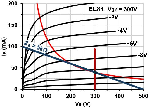 To draw a loadline for an SE power stage we can start by plotting the bias point.
Since there is almost no DC drop across the transformer winding resistance, the idle anode voltage will be practically equal to the HT voltage (vertical red line).
It is normal to bias an SE power valve to close to 100 percent of its maximum dissipation, so in this case we will assume a tentative bias curent of 12W/300V = 40mA (blue dot).
The load line always passes through the idle bias point, so we can now draw a likely-looking line from the knee of the 0V grid curve, through the bias point. Its slope will then tell us the transformer primary impedance.
The load line is allowed to cross the maximum dissipation curve, provided the bias point is below the curve.
In this case a 3k load line would pass nicely just below the knee, but looking at existing designs, and transformers sold for this sort of application, we find that 5k 5W is much more readily available –apparently everybody else has used that value before.
You could spend all day changing voltages and pushing lines around the graph, only to find that your choices are constrained by what is actually available.
To draw a loadline for an SE power stage we can start by plotting the bias point.
Since there is almost no DC drop across the transformer winding resistance, the idle anode voltage will be practically equal to the HT voltage (vertical red line).
It is normal to bias an SE power valve to close to 100 percent of its maximum dissipation, so in this case we will assume a tentative bias curent of 12W/300V = 40mA (blue dot).
The load line always passes through the idle bias point, so we can now draw a likely-looking line from the knee of the 0V grid curve, through the bias point. Its slope will then tell us the transformer primary impedance.
The load line is allowed to cross the maximum dissipation curve, provided the bias point is below the curve.
In this case a 3k load line would pass nicely just below the knee, but looking at existing designs, and transformers sold for this sort of application, we find that 5k 5W is much more readily available –apparently everybody else has used that value before.
You could spend all day changing voltages and pushing lines around the graph, only to find that your choices are constrained by what is actually available.
The maximum clean peak current swing available in a single ended stage is equal to the bias current, or 40mA, so the estimated clean output power is:
P = I^2 * Za / 2
P = 0.04^2 * 5000 / 2 = 4W
We know from the datasheet that the m-ratio (Ia0/Ig20) is about 8.7.
The idle screen current should therefore be about 40mA/8.7 = 4.6mA, making the total cathode current 44.6mA.
The bias voltage appears to be about -10.5V, suggesting we need a cathode resistor of 10.5V/0.0446A = 235 ohms, and it would dissipate 10.5^2/235 = 0.47W.
We will try 220 ohms (2W) as a close standard.
The cathode bypass capacitor will start boosting frequencies above:
f = 1 / (2 pi Rk Ck)
But in practice we would either throw in a generic, large value like 100uF, to fully bypass the cathode, or simply try different values to taste.
At switch-on, as the various supply voltages ramp up to their normal working levels, it is normal for a sustained voltage pulse to appear at the grid as the coupling capacitor charges up.
This can cause the output valve to pass abnormally high current for several seconds, limited only by the output transformer primary resistance, which in turn leads to abnormally high voltage across the cathode resistor.
This has been known to cause bypass capacitors to fail, even though their voltage rating is enough for normal running conditions.
For this reason the cathode bypass capacitor in the output stage should be generously overrated: four or five times the normal bias voltage is not unreasonable. For this example a 50V capacitor is suitable.
The grid-leak resistor (Rg) can be found by consulting the datasheet for the maximum allowable value in cathode bias.
For the EL84 it is surpringly large at 1M. We can afford to be a bit more conservative and use 470k.
The input coupling capacitor can be chosen in the usual way: by calculating from the desired cut-off frequency, or tweaking by ear.
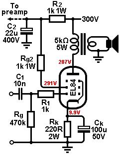 Throwing in some 1k stoppers for both grids, and a smoothing filter for the screen grid, we arrive at the final circuit.
Actual measured voltages are shown, and we find the idle dissipation has actually come out at 11W since we did not bother to account for the small drops across these various resistances.
We could tweak the bias hotter, but the valve should last longer this way, and it leaves some ‘headroom’ for accommodating replacement valve tolerances.
The measured output power was about 3W 'clean' (still over 10 percent distortion!) or 5W clipped.
Throwing in some 1k stoppers for both grids, and a smoothing filter for the screen grid, we arrive at the final circuit.
Actual measured voltages are shown, and we find the idle dissipation has actually come out at 11W since we did not bother to account for the small drops across these various resistances.
We could tweak the bias hotter, but the valve should last longer this way, and it leaves some ‘headroom’ for accommodating replacement valve tolerances.
The measured output power was about 3W 'clean' (still over 10 percent distortion!) or 5W clipped.
The maximum screen dissipation was found to be 3.5W during overdrive (with nominal load impedance) which is above the 2W datasheet limit.
Experience shows that an EL84 will handle this during actual playing conditions, but pushing the HT voltage even higher is known to causes problems.
(By contrast, without the screen stopper the screen dissipation reached over 5W, which is certainly courting disaster!)
We can see from the measured voltages that the total cathode current turned out to be 45mA, so we would need a power transformer capable of delivering this (plus a few milliamps for the preamp).
In a single-ended amp the total current remains fairly constant at any clean setting. During overdrive it will tend to fall slightly due to bias excursion.
By contrast, in class-AB push-pull amps the average current will increase with signal level, so the power transformer needs extra current capability to cope with this.
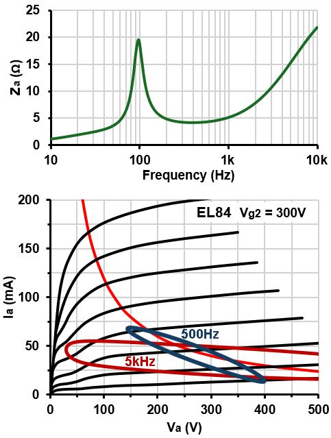 It is worth remembering that the loudspeaker is not a pure resistive load, but a reactive one.
Every speaker is slightly different, but most will have a large resonant peak somewhere near 100Hz, and a rising impedance at high frequencies, due to voice coil inductance.
At frequencies where the impedance is higher than nominal, the load line will rotate more horizontally.
Where the load is reactive (e.g. inductive) the load line will also open out into an elipse.
This can lead to much higher anode voltage swing, and higher screen dissipation, than the simple load line suggests.
This is why pushing the supply voltages up even higher, towards 350V and beyond, is a risk for the EL84.
It is also why you should not hook up a 16 ohm speaker to an 8 ohm transformer tap (conversely, reducing the speaker impedance is usually safe).
It is worth remembering that the loudspeaker is not a pure resistive load, but a reactive one.
Every speaker is slightly different, but most will have a large resonant peak somewhere near 100Hz, and a rising impedance at high frequencies, due to voice coil inductance.
At frequencies where the impedance is higher than nominal, the load line will rotate more horizontally.
Where the load is reactive (e.g. inductive) the load line will also open out into an elipse.
This can lead to much higher anode voltage swing, and higher screen dissipation, than the simple load line suggests.
This is why pushing the supply voltages up even higher, towards 350V and beyond, is a risk for the EL84.
It is also why you should not hook up a 16 ohm speaker to an 8 ohm transformer tap (conversely, reducing the speaker impedance is usually safe).
For example, the image on the right shows how a typical speaker impedance curve will actually appear when reflected across to the primary of our "5k" transformer, together with the reactive loadlines that occur with a 3Vpk grid drive, at two different frequencies.
These were produced by computer simulation and assume sinewave input, whereas with actual music the operating point will dance chaotically around the graph, barely averaging along our design load line!
|